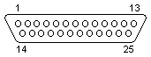
DB25 pinout and signals for the PC RS232 connector (serial and COM ports)
| Pin |
Name |
Direction |
Description |
| 1 |
SHIELD |
- |
Shield Ground |
| 2 |
TXD |
→ |
Transmit Data |
| 3 |
RXD |
← |
Receive Data |
| 4 |
RTS |
→ |
Request to Send |
| 5 |
CTS |
← |
Clear to Send |
| 6 |
DSR |
← |
Data Set Ready |
| 7 |
GND |
|
System Ground |
| 8 |
CD |
← |
Carrier Detect |
| 9 |
n/c |
- |
|
| 10 |
n/c |
- |
|
| 11 |
n/c |
- |
|
| 12 |
n/c |
- |
|
| 13 |
n/c |
- |
|
| 14 |
n/c |
- |
|
| 15 |
n/c |
- |
|
| 16 |
n/c |
- |
|
| 17 |
n/c |
- |
|
| 18 |
n/c |
- |
|
| 19 |
n/c |
- |
|
| 20 |
DTR |
→ |
Data Terminal Ready |
| 21 |
n/c |
- |
|
| 22 |
RI |
← |
Ring Indicator |
| 23 |
n/c |
- |
|
| 24 |
n/c |
- |
|
| 25 |
n/c |
- |
|
Note: Direction is DTE (Computer) relative DCE (Modem).
Note: Do not connect SHIELD(1) to GND(7).
Our software allows you monitor, log, debug and test any your RS232 or COM ports.
RS232 pinout and signals
Serial port pinout and signals
Full DB25 serial (RS232) port pinout and signals
DB9 pinout and signals