
TCP COM Bridge - Online help | TCP COM Bridge
About the program
General information
TCP COM Bridge is a utility program that works as an RS232-TCP/IP software converter and allows to forward data from a physical or virtual COM port to an Ethernet network. Using this program, you can turn any computer into a "serial device server." TCP COM Bridge lets you create a connection between two COM ports on two different computers, even via the Internet. This way, you can build distributed data collection systems using legacy software that supports COM ports only.
TCP COM Bridge lets you save money on buying hardware serial device servers, as a computer running the program can easily do the same task. You can connect or create up to 256 COM ports on one computer, which will simultaneously handle up to 256 RS232 devices.
Features:
•You can create connections for up to 256 physical or virtual COM ports.
•You don’t even need to have any physical COM ports on your computer.
•Other programs will not see any difference between a physical COM port and a virtual COM port created by TCP COM Bridge.
•You can transmit data using the TCP and UDP protocols both in the local network and over the Internet.
•When enabling data exchange over the Internet, TCP COM Bridge can handle dynamic IP addresses via a domain name.
•You can also create local connections on one computer.
•You can split data from one COM port into two or more streams (that is, use the program as a serial port splitter).
•TCP COM Bridge can be automatically launched as a service, create virtual COM ports, and set up network connections even before any user logs on.
Typical use cases:
In a separate section, you can find six typical use cases for Tcp Com Bridge.
LIABILITIES:
In no case shall we be liable for any loss or damages incurred by using this product.
The user can try out the demo version of this software product for twenty-one days. During the tryout period, the user can create only two connections on one computer, and the traffic through each connection is limited to 56 kilobytes.
Company website: https://www.aggsoft.com/
Limitations of the trial version
Limited version: Can be tried out for 21 days only. One virtual pair of serial ports can be created, and the limit on traffic is 65 KB.
Registered version: No limitations.
System requirements
CPU: Any CPU compatible with the modern Intel® x86 or x64 CPUs
Operating system: Windows 2000 Professional SP 4 and higher (all versions) x86 or x64.
Please note that Tcp Com Bridge is not compatible with Windows 9x, Me, or NT.
CPU speed
Minimal: 1 GHz.
It is recommended: 1.5 GHz or higher.
However, our program can successfully operate even on some of the slower multi-core CPUs.
System memory
Minimal: 512 MB
Recommended: 1024 MB.
Free disk space: The program needs about 5 MB, but its system log will also occupy some disk space.
Special access requirements: You must have the Administrator's privileges to configure our software. These privileges are necessary to install and manage a kernel-mode driver for virtual serial ports.
Notes for Microsoft Windows Vista or higher:
Since our program uses a driver to create virtual serial ports, the following conditions must be provided:
1.You need Administrator’s privileges to launch our software;
2.Our program’s shortcut will be placed on the desktop (Figure 1);
3.Windows Vista will ask your permission to continue the installation (Figure 2).
![]()
Figure 1: The program’s shortcut on the Windows Vista desktop

Figure 2: User Account Control dialog box
You can modify the security settings for your user account if you don’t want to see the warning shown above. Please google for the solution.
Installation
General installation requirements
If you are already using Tcp Com Bridge, close it. If Tcp Com Bridge is running as a service, temporarily stop the service via the Windows Control Panel.
If a beta version of Tcp Com Bridge is installed on your computer, uninstall it.
Launch the installation file.
During the installation, follow the installation wizard’s instructions.
By default, Tcp Com Bridge will be installed to the "C:\Programs Files\Tcp Com Bridge" folder on your system disk, but you can select a different path.
Notes for Microsoft Windows 2003:
During the installation of Tcp Com Bridge, Windows will twice ask your permission to install the driver (Figure 1). Please click "Yes."
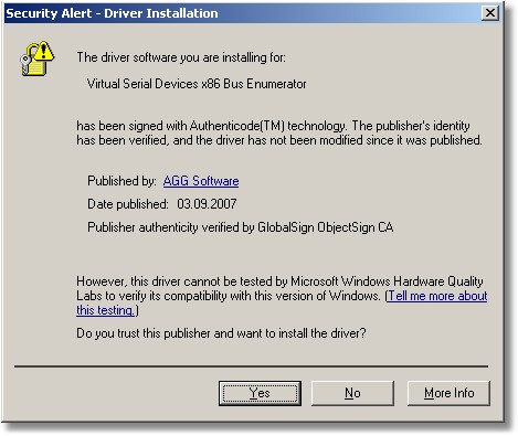
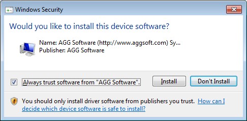
Figure 1: A warning displayed by Windows 2003 and Windows 7
Notes for Microsoft Windows Vista or higher:
Before installing Tcp Com Bridge, Windows will ask your permission to install the program (Figure 2). Please click "Yes."
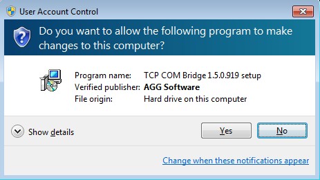
Figure 2: Request for permission to install the program
During the installation of Tcp Com Bridge, Windows will ask your permission to install the drivers (Figure 3). Please check the "Always trust software from AGG Software" checkbox, and then click the "Install" button.
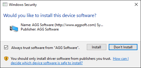
Figure 3: Request for permission to install the drivers
After installing Tcp Com Bridge, configure it step by step as described below.
Introduction
Key features:
•You don’t have to reboot your computer. You can create, connect, or remove virtual COM ports in real-time.
•You can create as many virtual COM ports as you need.
•Tcp Com Bridge is based on driver technologies and supports WDM, WMI, power management, plug-and-play, etc.
When you launch Tcp Com Bridge, its main window will open (Figure 1). You can use this window for configuration purposes. The picture below shows Tcp Com Bridge’s window, which consists of a few areas.
| 1. | Main menu - For more details about the commands in this menu, see the Menu section of this help file; |
| 2. | List of connections - A list of connections and their status; |
| 3. | Start-up mode - You can either set Tcp Com Bridge to start up automatically when Windows loads or leave the manual start-up mode. As soon as the program starts, it will automatically create all virtual ports as needed. |
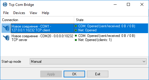
Figure 1: The main window
The main menu contains the following commands: File, Devices, View, and Help. Below you can find a description of each menu item. You can also call some commands via Hotkeys (see the section of Help). For each menu item, there is usually a hotkey and a toolbar button.
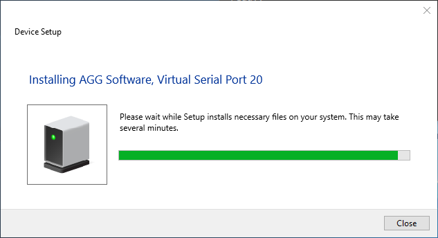
After adding a new connection, click "OK" in the configuration window to apply all changes. If the connection uses a virtual COM port, Tcp Com Bridge will add a virtual COM port to the system and install drivers as needed. On slow computers, it may take several minutes. Please wait for Tcp Com Bridge to add new virtual devices. During the process, some warnings can be displayed similar to the one in Figure 2. Such system messages will be displayed for each new virtual COM port. When Tcp Com Bridge is launched next time, it will use the drivers installed earlier, and no warnings will be displayed.
![]()
Figure 2: Tcp Com Bridge is adding a virtual serial port
After that, the virtual COM port will appear in the Device Manager (see Figure 3).
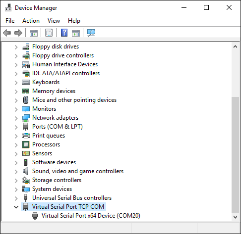
Figure 3: A virtual COM port displayed in the Device Manager.
"Devices" menu
Add new
Hotkey: Ctrl+N
How to open the menu - Right-click
Use this menu item to create a new connection.
Configure
Hotkey: Ctrl+C
How to open the menu - Right-click
This command opens a dialog box for editing a connection created earlier. This menu item is available only if a connection is selected in the list.
Delete
Hotkey: Ctrl+X
How to open the menu - Right-click
This command removes the selected connection from the list. The connection will be closed, and the virtual port will be deleted (if it has been specified in the connection settings to create a virtual port). This menu item is available only if a connection is selected in the list.
Delete all
How to open the menu - Right-click
This command clears the list of connections.
Reinstall all drivers
How to open the menu - Right-click
This command reinstalls all drivers used by the program to create virtual COM ports. It is recommended to use this command only if the program cannot create a virtual COM port or warns you about missing drivers.
COM port
Selecting this menu item will open the connection settings dialog (Figure 1).
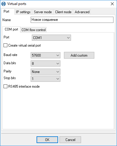
Figure 1: COM port settings
COM port
Port - COM port number. All possible options are displayed in the list. If you check the "Create virtual serial port" checkbox, the program will create a port with the specified number.
Note: COM port settings that you can see below are intended for a physical COM port only.
The parameters baud rate, bits, parity, and stop bits let you define the data transfer rate, the number of data bits, parity, and the number of stop bits, respectively.
To define a custom data rate, click the "Add custom" button. When a dialog box opens, enter the data rate in bauds, and click "OK." The new data rate will be added to the list.
RS 485 interface mode - This option enables the automatic control mode (using the RTS signal). When transmitting data, the program will always set this option active. It may be necessary for RS232-RS485 hardware converters.
Connect on demand - If this option is chosen, the application will only connect to the designated real COM port once a network connection has been made. If the "Close after inactivity" option is not selected, the disconnection happens immediately.
Close after inactivity - If this option is chosen, the program will check for activity on the chosen real COM port and disconnect from the COM ports if there is none for a certain amount of time in milliseconds. This lets other programs use the ports.
COM flow control
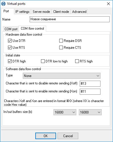
Figure 2: Hardware flow control settings
Hardware flow control
If hardware flow control settings are empty (by default), hardware flow control is disabled. You can combine settings to enable hardware flow control.
"Data reception control" stops data transmission by the remote device when the local input buffer is full. "Data transmission control" stops data transmission by your device when the remote device’s input buffer is full.
To activate data reception control, check the "Use RTS" or "Use DTR" checkboxes. If this feature is active, the RTS or DTR modem control signals are suspended when the amount of incoming data reaches 90 percent of the buffer size. The remote device must recognize these signals and suspend data transmission while the signals are in a low state.
When the applications receive the characters, the buffer use will be reduced to not exceed 10 percent of the buffer size. When that happens, the modem control signals will resume. The remote device must recognize these signals and resume sending data.
To activate data transmission control, check the "Require CTS" or "Require DSR" checkboxes. If one or both of these options are turned on, the Windows communication driver will not send data if the remote device does not provide the respective modem state signal (CTS or DSR). The remote device must resume and suspend these signals when it is necessary to control the data flow.
Please note that data flow control using RTS and CTS is more popular than using DTR and DSR.
Software flow control
This subprogram provides one or both automatic software flow control options based on the value considered as a property.
"Data reception control" stops data transmission by the remote device when your local input buffer is full. "Data transmission control" stops data transmission by your device when the remote device’s input buffer is full.
To activate data reception control, set "On receiving" or "Both" for the "Type" property. If this control is active, Xoff characters will be sent when the amount of incoming data reaches 10 percent of the buffer size. The remote device must recognize the signal and suspend sending data.
When the applications receive the characters, the buffer use will be reduced to not exceed 10 percent of the buffer size. At this moment, Xon characters will be sent again. The remote device must recognize these signals and resume sending data.
To activate data reception control, set "On transmitting" or "Both" for the "Type" property. In that case, 10 percent or 90 percent of the buffer size will not be used, respectively. If data transmission control is active, the communication driver will suspend sending data each time a Xoff character is received. The driver will not resume sending data until it receives a Xon character or until the user sets "None" for the "Type" property.
Software flow control can be set for receiving data, sending data, or both. However, not to use a lot of devices for sending data, set "Receive" for the "Type" property. If data transmission control is active, the remote device (in this case, your device) can send special codes to signal that it suspends or resumes data transmission. By default, the hexadecimal character 0x11 received from the remote device signals the COM port driver to start receiving data, and the hexadecimal character 0x13 signals to finish receiving data.
Input/output buffer size - the size of the program’s internal buffer. Some COM port drivers may not support the default buffer size. In that case, set a smaller buffer size.
IP settings
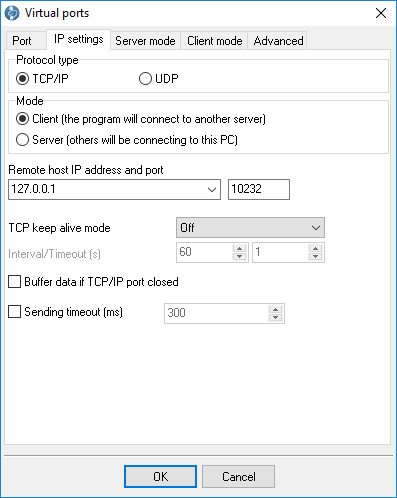
Figure 3: IP settings
Protocol types
TCP - a reliable protocol, probably the one most widely used in IP networks. The advantage of using this protocol is its ability to maintain and control a connection between computers. TCP also inherently supports data integrity checking. Some of this protocol’s drawbacks are its data transmission redundancy and additional time spent establishing a connection.
UDP - a protocol that does not require establishing a connection for data transmission. Like TCP, UDP works as the upper layer in IP networks. But unlike TCP, UDP doesn’t help to deliver data and doesn’t have any built-in error controls. But this protocol allows to directly send and receive data packets, while applications can check data integrity on their own and, if necessary, resend data. UDP can be used, for example, to send small multicast packets. When using this protocol, applications "send and forget."
Connection
In Tcp Com Bridge, each connection can work as:
| 1. | Client. You need to specify the remote computer's IP address and port that runs the TCP/IP server that you want to connect to. The IP address you enter while configuring Tcp Com Bridge can also be a domain name (like www.yourserver.com), or a computer name in the local network. For example, to connect to a computer named "Plant1" in the local network, you can simply enter "Plant1" in the IP address input field, instead of the proper IP address. That may be handy for configuring Tcp Com Bridge as a client if IP addresses in your network are assigned dynamically. So it may be easier to use a computer name instead of an IP address. |
| 2. | Server. In this mode, you need to specify the computer's IP address on which the program runs and a port to listen to. If your computer has multiple network adapters (network interface cards), Tcp Com Bridge will display a list of IP addresses for each network interface card (NIC) installed on your computer. In that case, select the IP address of the network interface that you want to use. For Tcp Com Bridge to operate as a server, you must assign it at least one network card with an IP address. In Windows, TCP/IP may be configured for automatic assignment of an IP address for the computer. In that case, you need to ask your system administrator to assign your computer a static IP address and allocate that IP address to the selected network interface. You can also enter 0.0.0.0 as an IP address to make the programs listen to all IP addresses assigned to the computer. |
IP address and port - The address and port of a remote server (in the client mode) or a local IP address and port (in the server mode).
Sending timeout - You can set a time interval for "grouping" data to send all of them in one IP packet. Doing that can speed up sending data if the COM port frequently receives small data portions.
The following settings apply only to TCP/IP when the server or client mode is used:
TCP keep-alive mode - If this option is turned on, the program will be sending special data packets at the specified interval. Suppose the client (or the server) doesn't respond during the specified timeout. In that case, the program will automatically break the connection as the lack of response indicates a loss of connection with the client (or the server). If you set the "System" keep-alive mode, the program will use interval and timeout values predefined in Windows.
Buffer data if TCP/IP port closed - If you turn on this option, the program will put all data received from the COM port into a temporary, internal buffer whose size you can define via the "COM port" tab. When the connection is reestablished, the program will first send the data from the buffer.
Server mode
These settings (see Figure 4) only apply to the server mode.
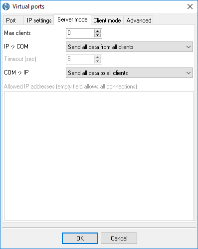
Figure 4: Additional server settings
Max clients - You can limit the number of clients simultaneously connected to the server. That lets you optimize the server load if there are too many clients. Zero means that the number of connections is not limited.
Allowed IP addresses - This option is active in the server mode and lets you define one or more IP addresses allowed to connect to the server. Any connection attempts originating from other IP addresses will be rejected. This setting is very useful if you transmit data over the Internet or if the server is connected to a big corporate network. You can enter multiple allowed addresses, one address per line. If you leave the field empty, Tcp Com Bridge will accept connection attempts originating from any IP address.
The IP → COM and COM → IP settings let you select the data transfer mode from IP to the COM port and vice versa. You can block data transfer in one or both directions.
Enable UPnP - the UPnP function enables auto-discovery of an internet gateway in your local network. If the program finds the gateway, it will send a command to redirect data for the current computer's configured IP port.
Special mode - in this mode, the program can create a bridge connection between two TCP clients. One TCP client connection should be initiated from the current computer. In this case, the program provides data exchange between two TCP clients, and the program does not send data to a COM port. This mode allows you to send data from an application that can work in the TCP client mode to a remote computer with a dynamic IP address or behind NAT.
Client mode
Using these settings (see Figure 5), you can allow or forbid data transfer in the client mode.
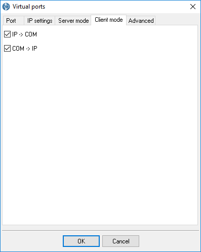
Figure 5: Additional client settings
"View" menu
Icons
There are four options for displaying icons in Tcp Com Bridge: Big icon, Small icon, List, and Table. In the table mode, the status of each COM port and network connection is displayed too.
Auto arrange icons
This way, you can find what you need more quickly.
Command line parameters
-p SerialNo
Connect virtual COM port with number SerialNo. SerialNo must be greater than zero.
-u SerialNo or 0
Disconnect virtual COM port with number SerialNo. To disconnect all listed devices, use 0.
-e SerialNo or 0
Unmount virtual COM port with number SerialNo. To unmount all listed devices, use 0.
-i <INF_File> <Hardware_ID>
Install the INF_File drivers for the Hardware_ID device.
-ia
Install all necessary drivers.
-r <Hardware_ID>
Uninstall the Hardware_ID device.
-ra
Uninstall all drivers installed by the program.
-s0
Do not show any messages.
-s1
Write messages to the Windows event log.
-s2
Show a message box (by default).
Note: Make sure that you enter parameters in the correct order. For example, the following command installs all necessary drivers without displaying any messages:
tcpcom -s0 -ia
FAQ and known issues
Q: I want to handle (create or remove) connections programmatically.
A: You can do that via the command line.
Q: I cannot open a virtual serial port.
A: Invoking the "CreateFIle" function with a string like "COM%d" lets you open only the ports COM–COM9. To open other ports, use a string like "\\.\COM%d" instead. In that case, you can open COM ports with any number.
Q: How can I get a list of all virtual COM ports?
A: You can use the SetupAPI functions and look for all devices of the class with the GUID {487ECAF4-213D-4d17-AA07-2F91078B619D}.
Unable to install Virtual Port Driver
The problems described below may occur when creating a virtual COM port configuration.
Problem 1
The program hangs at the moment of driver installation.
Some third-party antivirus programs may block the driver installation. Try temporarily disabling your antivirus.
Our users have reported issues with:
Avast Antivirus Free
NANO-Antivirus
Antiy-AVL
Note: If your antivirus trial period has expired and it reports that it is not working, it does not mean that it is completely disabled.
Problem 2
A virtual port won't show up in the Ports group (COM and LPT).
The virtual devices created with our program appear in a separate group named Virtual Serial Port.
Problem 3
The virtual port is available, but it is labeled with an exclamation mark in Device Manager.
This problem may occur when you try to create a port with a number that already exists in the system. To resolve the issue, try creating a virtual port with the number COM20. If you need to create a port with an already existing number (for example, COM1), then follow these steps:
1.Close all programs that might use COM1.
2.Find COM1 in Device Manager.
3.Right-click on it.
4.Select Properties and go to the Port Settings tab.
5.Click Advanced.
6.In the COM Port Number drop-down list select a free port and click OK.
7.Wait until the operating system applies the changes in the port number. You may need to reboot your computer.
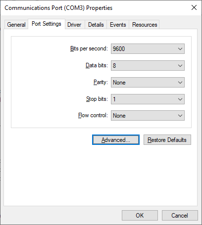
Fig. 1. COM port settings
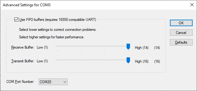
Fig. 2. Selecting a new COM port number
Problem 4
Unable to create a COM port. A new device won't show up in Device Manager, or it is labeled as unknown.
This problem is due to a failure to install the virtual port driver. Our driver has a valid digital signature, and there should be no problem installing it on all supported versions of Windows, including 64-bit editions.
Solution 1
The driver can only be installed with administrator rights. Please make sure that your account has the appropriate permissions.
Solution 2
The operating system cannot verify the digital signature of the driver. This problem may occur on older operating systems when there is no Internet connection, and no updates installed. You need to update your operating system or install updated certificates using rootsupd.exe in the program folder.
For 64-bit Windows: c:\Program Files (x86)\TCP COM Bridge\inf\
For 32-bit Windows: c:\Program Files\TCP COM Bridge\inf\
Solution 3
In operating systems released later than Windows Vista or Windows Server 2012, your PC or server's security policy may prohibit installing the driver for all new devices or the selected device classes. Such a policy may be implemented at the organization level if your computer is connected to the domain.
The easiest way to check your security policy is to run the rsop.msc snap-in:
1.Use the Windows key + R shortcut.
2.Type rsop.msc and press Enter.
3.The snap-in will check the existing security policy and display the enabled rules.
4.You need to make sure that there are no prohibiting or restricting rules in the group policy:
Computer Configuration - Administrative Templates - System - Device Installation - Device Installation Restrictions.
Policy settings:
•Prevent installation of removable devices.
•Prevent installation of devices not described by other policy settings.
Make sure you disable these settings during the installation of a new device. To change policy settings, contact your system administrator if necessary.
To configure policy settings, you can use the gpedit.msc snap-in.
Note: Group Policy Management Editor (gpedit.msc) is not installed by default in Starter, Home, and Home Premium editions. You will need to install it or use the registry editor.
1.Use the Windows key + R shortcut.
2.Type gpedit.msc and press Enter.
3.Go to Group Policy Editor: Computer Configuration - Administrative Templates - System - Device Installation - Device Installation Restrictions.
4.Disable the settings "Prevent installation of removable devices" and "Prevent installation of devices not described by other policy settings." Double-click on the name of the setting in the list and select Disabled.
5.In the program TCP COM Bridge, select System (Devices) - Reinstall drivers. Please wait until the installation process has ended.
6.Create the necessary virtual ports.
7.Save the settings.
8.Wait until the drivers for the new virtual ports are installed.
How to Use the Registry Editor
1.Type "regedit" (w/o quotes) in the Start menu search box
2.Right-click on the found Registry Editor application and select Run as Administrator.
3.Go to the branch HKLM\Software\Policies\Microsoft\Windows\DeviceInstall\Restrictions.
4.Set the value DenyRemovableDevices (REG_DWORD) to 0 (disabled).
5.Set the value DenyUnspecified (REG_DWORD) to 0 (disabled).
6.Restart your computer to apply the changes.
7.In the program TCP COM Bridge, select System (Devices) - Reinstall drivers. Please wait until the installation process has ended.
8.Create the necessary virtual ports.
9.Save the settings.
10.Wait until the drivers for the new virtual ports are installed.
Upon completion of virtual port installation, you may configure the initial values of the policy settings.
Solution 4
Make sure that driver installation from Windows Update is enabled.
1.Control Panel - System and Security - Advanced System Settings - Hardware - Device Installation Settings.
2.Select "Yes (recommended)".
3.Click OK and save the changes.
Solution 5
If the steps above do not help, the Windows may be corrupted. Then it is recommended to check the system files:
1.Type "cmd" (w/o quotes) in the Start menu search box.
2.Right-click on the Command Prompt application and select Run as Administrator.
3.In the command prompt, type "sfc /scannow" and press Enter.
4.The utility will check the Operating System for system file corruption.
5.Please wait until the system file check is complete.
Solution 6
Failure to install the driver may be due to a corrupted database of the device.
1.Follow steps 1 and 2 from solution 5.
2.To run the check, type in the command line: Dism /Online /Cleanup-Image /ScanHealth
3.To fix errors, type in the following: Dism /Online /Cleanup-Image /RestoreHealth
Typical use cases
You can use Tcp Com Bridge to solve different problems. Below you can read about the most typical use cases.
1. Convert a computer into a serial device server with multiple ports.
A serial device server (sometimes also referred to as a "terminal server") is a hardware device that lets you connect various devices with the digital serial interface (controllers, lab equipment, industrial sensors, barcode scanners, etc.) to the Ethernet network, and enables data exchange with them via a TCP/IP port.
Tcp Com Bridge fulfills the same function, only using a Windows computer with COM ports. You can configure Tcp Com Bridge to handle multiple COM ports (up to 256 ports). For each COM port, a separate TCP/IP port will be used in the server or client mode.
By using an ordinary computer and Tcp Com Bridge, you can save a lot on hardware.
For example, a special-purpose server with 16 ports (a standard industrial configuration) costs about $2000. If you buy a computer (with a built-in network adapter, hard drive, etc.) for $500 and a PCI or PCI-E input-output card for 16 ports for $500, you can save about $1000. To save even more money, you can
a. Use RS232-USB converters (you can connect multiple converters to a modern computer).
b. Use an existing computer instead of buying a new one.
Moreover, while Tcp Com Bridge is running in background mode, you can use that computer for doing other things, not only as a terminal server.
Unlike most hardware terminal servers, Tcp Com Bridge lets you simultaneously create multiple TCP/IP connections. You can use Tcp Com Bridge to build fail-safe systems, as it can monitor the state of connection, reconnect after a loss of connection, and buffer data while no connection is available.
2. Send data over a TCP/IP network from applications that can normally work with COM ports only.
Say, a legacy application can use COM ports only. By using two copies of Tcp Com Bridge, you can transmit data over many miles instead of over several feet. One copy will be operating as a terminal server on the remote computer, and the other copy as a client on the computer running the legacy application. The data will be transmitted over the TCP/IP network, but the legacy application will "think" that it works with a COM port.
3. Use a remote computer’s COM port as if it were a local COM port.
Say you need to receive data from a device connected to a COM port on another computer in your local network. To do that, configure Tcp Com Bridge as a terminal server on the remote computer. Then you can either receive data on your computer via TCP/IP (for example, using the Hyperterminal) or install a second copy of Tcp Com Bridge on your computer and configure the program as a client, also creating a virtual COM port. In that case, you can exchange data with a remote COM port via the local COM port.
4. Use a local network or the Internet instead of using a cable connection.
Run Tcp Com Bridge as a TCP/IP server on one computer, and configure the program to use an existing COM port. Then run a second copy of Tcp Com Bridge as a TCP/IP client, and configure it to connect to the first copy. The second copy must also use the existing COM port. In that case, all data incoming to the COM port on Computer #1 will pass through the first copy of Tcp Com Bridge, the network cable, the second copy of Tcp Com Bridge, and then will go out through the COM port on Computer #2. Data can also go the other way. The advantage of using such a connection is that you can simultaneously send data to multiple computers.
5. Split the data from an existing COM port into several COM ports.
Usually, Windows doesn’t allow opening the same serial port by more than one application. Tcp Com Bridge lets you bypass that limitation. In this case, you are using one copy of Tcp Com Bridge with several connections configured. One connection works in the TCP/IP server mode with a physical COM port. The other connections work in the client mode, establishing a connection with the TCP/IP server and creating virtual COM ports. Say, you can split the physical port COM1 into two or more virtual COM ports (for example, COM10 and COM11). You can also configure the system in such a way that data from COM1 is sent to COM10 and COM11, but transmission in the other direction goes only through COM10.
6. Redirect a TCP/IP port.
Configure two connections in Tcp Com Bridge. Connection #1 should work as a TCP/IP server and create a virtual COM port. Connection #2 should also be configured as a TCP/IP server but using a different TCP/IP port. Note that Connection #2 must use the port created by Connection #1 (not to create another virtual COM port). In this case, two TCP/IP ports are connected via one virtual COM port.
Selecting a TCP/IP port number
When configuring TCP/IP connections, Tcp Com Bridge allows you to choose any TCP/IP port number. The range of possible port numbers is from 1 to 65535. Port numbers from 1 to 1000 may be used by the operating system or other utility programs. But you can freely use TCP/IP port numbers greater than 1000. So we recommend assigning port numbers greater than 1000.
Please note that if you select a port, it can be already used by other programs. Two programs cannot simultaneously use the same port. Even if the port that you selected during configuration is free, that does not guarantee that it will not be used later by another program.
If you encounter an issue with your port being used by another program, change the TCP/IP port number.
Selecting a COM port number
Tcp Com Bridge allows you to create a virtual COM port with any number. When choosing a number for the virtual port, you should not select any port numbers that already exist on your computer. You can check which ports are in use via the Device Manager. Please note that Device Manager displays not all existing COM ports. To check if a port already exists, try creating a configuration without creating a virtual COM port. If there is no such port on your computer, Tcp Com Bridge will display a message informing you about that. As a rule, port numbers starting from 10 are not used.
Configuring the program to run as a service
You can configure Tcp Com Bridge to run as a service in all Windows operating systems, starting from Windows 2000. It will allow the program to set up connections and create virtual COM ports automatically as soon as Windows loads before any user logs on. In this mode, Tcp Com Bridge runs in background mode and usually is not noticed by users. To configure the program to run as a service, do the following:
1. Run Tcp Com Bridge and configure connections as necessary.
2. Select the "Windows service" operating mode via the program’s main window.
3. Test all connections to make sure that they work properly.
4. Close the program by clicking the "Exit" button and agreeing to close all active connections.
5. If you reboot the computer, the service will be launched automatically. You can also launch the service manually without rebooting the computer: Control Panel → Administration → Services → Tcp Com Bridge.
6. You can check if the service is running via the Task Manager. In the list of processes, you should see tcpcom.exe
Change connection settings or add new connections as follows:
1. Launch Tcp Com Bridge by clicking its icon on the desktop or via "Start → Programs."
2. Agree to launch the program in restricted mode (because it is already running in background mode).
3. Change the program’s settings as you need.
4. Go to "Control Panel → Administration → Services" and restart the Tcp Com Bridge service.
To disable the service mode, do the following:
1. Go to "Control Panel → Administration → Services."
2. Stop the Tcp Com Bridge service.
3. Open the Properties dialog for the Tcp Com Bridge service.
4. Change the start-up mode to "Manual."
Using the program to transmit data via the Internet
You can configure Tcp Com Bridge to transmit data via the Internet. To enable data transmission, you might need to change the network settings on your computer or the router in your network.
Most computers are not connected directly to the Internet, so other computers may be unable to connect directly to your computer via the Internet and transmit data.
How to check whether your computer is connected directly to the Internet?
If your network address belongs to one of the ranges listed below, it means that your computer is in a local private network and is connected to the Internet via a router:
10.0.0.0 - 10.255.255.255
172.16.0.0 - 172.31.255.255
192.168.0.0 - 192.168.255.255
For more details, read this article: https://en.wikipedia.org/wiki/Private_network
Your public IP address on the Internet may be entirely different. You can check it via Google:
https://www.google.com/search?q=my+ip+address
To configure a connection for Tcp Com Bridge operating as a client, you only need to know the other computer's public IP address on the Internet.
To configure a connection for Tcp Com Bridge operating as a server, you need to configure port forwarding on your router. Port forwarding on the router lets you redirect all data, coming to the specified public IP address and port, to the local IP address.
For example, your address in the local network is 192.168.1.12. Your public IP address is 66.249.75.147. All clients will be sending data only to your public IP address. The router will forward data to 192.168.1.12, implicitly binding your local IP address to your public IP address.
Note: For Tcp Com Bridge to operate as a server, it must run on a computer with a static local IP address. That’s because the router is configured to forward data to a specific address only.
How to configure the router to redirect data?
1. Open your router’s control panel. Usually, you configure the router via a web browser. Try entering http://192.168.1.1/ in the address bar.
2. On the control panel, look for "Port Forwarding" or "Virtual Server" settings.
3. Add a data forwarding rule.
Example:
Local port: 10232
Local IP address: 192.168.1.12
Remote port: 10232
4. Save the changes, and reboot the router.
For more details about configuring port forwarding for any vendor's router model, visit this website: https://www.portforward.com/. If your router model is not listed, try reading instructions for similar models.
Dynamic public IP address
Having a dynamic public IP address may not let Tcp Com Bridge operate as a server. Each time you connect to the Internet, your public IP address may change, so a remote computer will be unable to connect to a predefined IP address. If you don’t know what type of IP address you have, ask your Internet service provider.
Dynamic DNS services can solve this problem by binding your dynamic IP address to your permanent domain name. For example, you can use these dynamic DNS services:
If you register at such a website, you will get a permanent domain name. If you install special soft-ware from the DNS service provider on your computer, you can automatically update your dynamic IP address's binding to the domain name.
Many state-of-the-art routers have built-in support for dynamic DNS services.
Firewall
Another thing that may hinder the transmission of data via the Internet is the firewall. The firewall’s purpose is to prevent any unauthorized transmission of data. All modern operating systems have a built-in firewall. All-in-one antiviral bundles include a firewall too.
When Tcp Com Bridge attempts to use any TCP port for the first time, the Windows Firewall will warn. To let Tcp Com Bridge operate properly, you must allow it to connect to the network. You can see an example of a firewall warning in Figure 1.
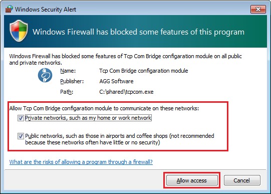
Figure 1: Firewall warning
If you use a third-party firewall, you may also need to configure it to let Tcp Com Bridge connect to the network. Please refer to your firewall’s manual, and add Tcp Com Bridge to the list of exceptions.