Advanced Serial Data Logger

for Windows 9x/Me/NT/2000/XP x86,x64/2003 x86,x64/Vista x86,x64. Latest version: 3.5.14 build 911. September 11, 2008.

Trust In Confidence!

PBX data logger. Capture a serial data from PBX systems.

Problem scenario:

I can’t seem to be able to write the log of our local PBX system into my SQL 2000 database. I have installed the ODBC plug-in and have tested the ODBC connection through the ODBC administrator and everything seems to be working. Now, I wish to parse and write a log of the data to a file in my database.

PBX data

Fig.1. PBX system captured data by the serial data logger software

Requirements:

  • Advanced Serial Data Logger (ASDL) Professional or a trial version;
  • ASCII data parser and query plug-in for Advanced Serial Data Logger;
  • DDE server plug-in for the data logger(optional);
  • ODBC database plug-in for the data logger.

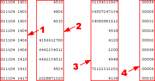
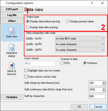
It is assumed that:

You have configured all communication parameters (baud rate, number of data bits, flow control etc) in the data logger and you are able to receive all data without communication errors.

Solution:

The image (Fig.1) above shows a simple data flow. Each record has a fixed size and a fixed position for each item. As an example, for a single record, all non-printable characters with a code less than 20 Hex are selected for display. The indicated radio buttons are set as shown below.

PBX data logger. Data view mode.

Fig.2. PBX data logger. Serial data view setup

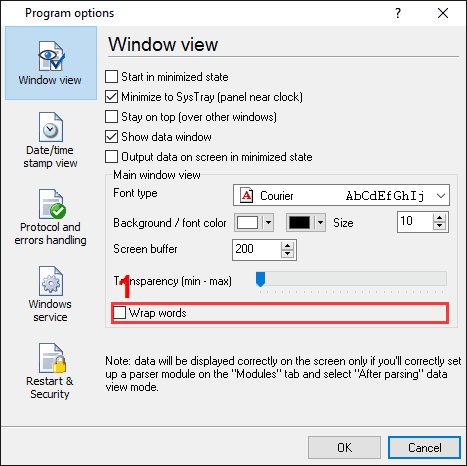
If your data flow is fast, then ASDL will not split your data into separate lines and you will get one long line on the screen. For this reason, it is necessary to tick the "Wrap words" tick box. This effectively adjusts the line length to the width of the window (Fig.3, pos #1).

PBX data logger. Window view

Fig.3. PBX data logger. Serial data word wrap

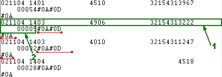
Click the "OK" button and attempt to receive data from a serial port. You should get something like the image below.
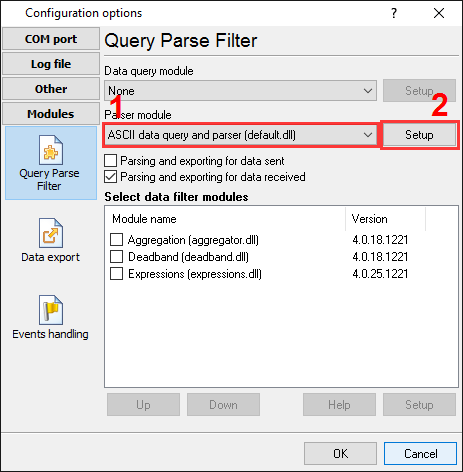
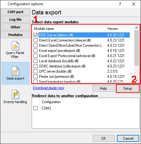
PBX data logger. Data received

Fig.4. PBX data logger. Data received.

This is the other view of the data received. Notice that all non-printable characters were replaced with their code i.e. #0D. It is clear from the data screen above, that the data block (within the green rectangle) ends with #0A#0D#0A (underlined by red). In this example, our data block contains two parts namely, 1 and 2. The part #2 was adjusted to the width of the window. Both of these parts should be interpreted as a single whole.

We are now ready for configuring of the modules. First, select the "ASCII data query and parser" plug-in (Fig.5, pos. #1) from a drop-down list. Then, enable a parsing option for data received (Fig.5, pos. #2) and select the necessary data export plug-ins. The DDE server (Fig.6, pos. #3) will help to check the accuracy of the parser's configuration. The "ODBC database" plug-in will write the data to the Microsoft SQL Server 2000 (Fig.6, pos. #4).

PBX data logger. The data parser plug-in setup

Fig.5. PBX data logger. The data parser plug-in setup.

PBX data logger. Data export plug-ins setup

Fig.6. PBX data logger. Data export plug-ins setup.

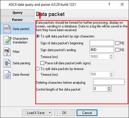
Next, open the ASCII parser and query configuration window (click the "Setup" button near the drop-down box as indicated on pos.#1 on Fig.5). A dialog window will appear on the screen (Fig.7) about the data packet.
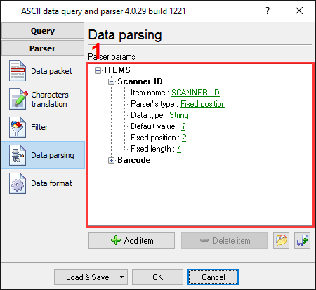
PBX data logger. Parser configuration window

Fig.7. PBX data logger. Parser configuration window.

The configuration process should be very simple if you have examined your data flow in the data logger window (Fig.4). You should type in the same as in the data logger window in fields 1 and 2. Field #1 marks the beginning of the data block and the field #2 marks the end. In the example, our data block does not contain a start marker. Therefore, this field is left empty. The values to be typed in here are as underlined in red in Fig.4 above.

The next tab is a very important part of the parser configuration. The data parser uses this information for data extraction from the data block. In the example, the data block contains 4 data items (see Fig.1) namely: date and time, calling party number, called party number and call length in seconds, which should be separated out to different variables. Later, these variables will be used in the data export and will be placed in different columns of our SQL2000 database.

PBX data logger. Parser items

Fig.8. PBX data logger. Parser items.

Any new items may be added by clicking the "Add item" button (Fig.8, pos. 7). Before adding an item the program will ask you about an item description. You can type any characters here, which will help you to remember a variable's content. For this example all 4 variables with their corresponding descriptions have been added.

Each parser item has a number of properties:

  1. Item name - this name will be bound to a column in the data export plug-in. It is a limited text description and cannot contain spaces and a few other characters;
  2. Parser's type - is a method, which the program will use for data extraction. Our parser has a few methods from simple to most powerful. In this example, where data is being placed in fixed place, we can use the simple method - fixed position. This method allows the extraction of any number of characters from any fixed position of the data block;
  3. Data type - is the data type of the characters extracted. For example, you can specify FLOAT or STRING data types. The data will be converted to the conversion type later, in the data export module. The data type here is being used for formatting of the value, which will be specified on the "Data formats" tab later. In the example, the "Call date and time" field has the DateTime data type, the "Call len" field has the Integer data type. All other fields have the String data type;
  4. Default value - the value specified here is to be used when data cannot be extracted from a data block;
  5. Fixed position - is the position of the first variable's character in our data block. The minimum value is 1;
  6. Fixed length - is the number of characters, which will be transferred to a variable. The minimum value is 1.

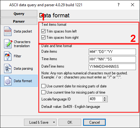
All other items have the same parameters, a position, a length and a data type of other.

In the next tab, you can specify basic format options as per (Fig.9). If you had specified the data type "String" in the item's parameters, then the first two options allow you to remove blank spaces from a value. Our called and caller number contain blank spaces at the start of a value. The second option allows you to convert the date time string to a field with the date time data type. We specified MMDDYY HHNN here, according to the specification above. For a detailed description of formatting characters, please, see the help file.

PBX data logger. Format of items

Fig.9. PBX data logger. Format of items.

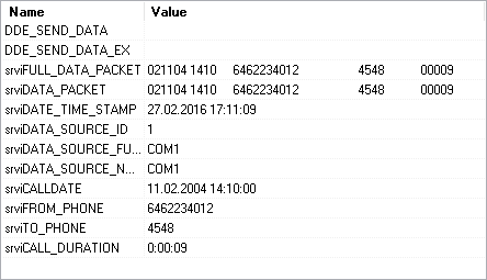
Other options are unnecessary in our case, because all our items do not have the date or time data type.

Click the "OK" button and close the parser configuration window. Then click the "OK" button in the options window.

Now that our parser is ready it is time for testing it. Connect your device and power it on if necessary. Check to see if you are able to receive a data block from the specified serial port. If the parser had been correctly set up, then you should see all the variables names and their values (Fig.10) in the DDE server window below.

PBX data logger. DDE server window

Fig.10. PBX data logger. DDE server window.

All the variables are now ready for export to the SQL2000 database.

If you want to export data to other destinations, please read the instructions by following the links below:

Weight data logger and Microsoft Access;
Capture a serial data to Microsoft Excel;
Log scales weight data to Microsoft Excel;
Combine a data of two different com-ports to one MySQL table row;
Real time charting in Microsoft Excel;
Send serial port data to Excel via DDE.

Export data to Microsoft SQL Server 2000 database

Note: This configuration process is complex and might prove to be difficult for the unskilled user. You may wish to consult an expert. In Australia, contact Power Business Systems on 08 6250 7900.

It is assumed, that you have access to the database and can manage it. First of all, create a table in a database. Select any existing user database or create a new one. The simplest way is to use the Enterprise Manager of the Microsoft SQL Server. This software ships with a standard distribution and you can find it in the "Microsoft SQL Server" menu in the "Programs" group. In this example, we created a table called "PBX_LOG_DATA" in the test database "Northwind". A structure of the table is shown in Fig.11 below.

PBX data logger. SQL table

Fig.11. PBX data logger. SQL table.

Note that 4 columns have been added to the table, for all variables from the parser. You can add more columns if you want or use tables with your structure.

Note: You should specify unique columns names. Names which are reserved words of ANSI92 SQL cannot be used. In this example, we could use the name “Datetime” for the first column. However, as it is a reserved word, the prefix "d_", has been added to distinguish it from the reserved word.

Now that our table is ready, the security within SQL Server has to be addressed. Within SQL, each user may be configured for access to specific tables only. In our example a new user could be created, or access could be granted for the table above to an existing user account. It is also possible to connect using an administrator account, which has full access rights. However, it is suggested that the administrator account be used for testing only. We have created the user with the name of "uvt", and set up "Northwind" as the default database for it (see Fig.12 below).

PBX data logger. The new user

Fig.12. PBX data logger. The new user.

By default, the user has been assigned the "public" role only. Access should be granted for this role for writing to our table (Fig.13).

PBX data logger. The

Fig.13. PBX data logger. The "Public" role rights.

The "ODBC database" plug-in uses an ODBC alias for accessing the SQL Server 2000 database. This can be configured using the "ODBC data source administrator” control panel applet. You can find this applet in the "Control panel", under "Administration" group in Windows 2000. Once you have located this group, click the "Setup" button on the "Connection" tab (Fig.21 pos. #3 ). In the "ODBC data source administrator" you should create a user or system ODBC alias. System ODBC aliases (select the tab at the pos. #1 on Fig.11) are used with a service mode of ASDL. We will add a new user alias. You can do this by clicking the "Add" button (pos. #2 on Fig.14).

PBX data logger. ODBC data source administrator

Fig.14. PBX data logger. ODBC data source administrator

A configuration wizard window will appear (Fig.15). On the first page you should select an SQL server driver (pos. #1 on Fig.15) and click "Next" button. If the drivers list does not contain the SQL Server driver, then you should install Microsoft SQL Server client applications from the same CD, as Microsoft SQL Server 2000.

The SQL Server alias setup. Step #1

Fig.15. The SQL Server alias setup. Step #1.

On the next page (Fig.16), specify an ODBC alias name (TEST in our case), a small text description and select your SQL server from the drop-down list. If a server does not exist in the list, then check that the server has been started and it is available over a network. After filling out all the options, click the "Next" button.

The SQL Server alias setup. Step #2.

Fig.16. The SQL Server alias setup. Step #2.

On the next page (Fig.17) we have selected a SQL Server authentication (pos. #1), because a new user has been added. Next enter the user name and password (pos. #2).

The SQL Server alias setup. Step #3

Fig.17. The SQL Server alias setup. Step #3.

In the following page (Fig.18) we have selected our test database - "Northwind" and have left the other options without any changes.

The SQL Server alias setup. Step #4.

Fig.18. The SQL Server alias setup. Step #4.

On the final page (Fig.19) you should test the connection. Just click the "Test data source" button.

The SQL Server alias setup. The final step

Fig.19. The SQL Server alias setup. The final step.

Ok, the database and table are both ready. Next go to the "ODBC database" plug-in configuration window and open it using the common option on the left of the window (Fig.20).

PBX Data Logger. ODBC database. Enabling connection

Fig.20. PBX Data Logger. ODBC database. Enabling connection.

The radio button at pos. #1 enables writing to the database and the tick-box at pos. #2 specifies that the database is to be kept open. This serves to minimize the writing time, at the same time locking out other users from writing.

On the second page "Connection" (Fig.21) you can specify the parameters of your database. Here select your ODBC alias name which you created above at pos#1. Note that if you configured an ODBC alias after opening the configuration window, please close it first, re-open it, and then retype your login and password at pos. #2.

PBX Data Logger. ODBC database. Connection options

Fig.21. PBX Data Logger. ODBC database. Connection options.

In our example no additional attributes are specified.

On the third page "Errors handling" of "ODBC database" plug-in (Fig.22), specify how the software should react to errors which occur while writing to a database.

PBX Data Logger. ODBC database data logger. Error handling

Fig.22. PBX Data Logger. ODBC database data logger. Error handling.

In this example, the last option (pos. #1) was checked as the data is important and we require the program to operate regardless of the error. The other variants are normally used when testing the plug-in module with a new database.

The last page "Binding" (Fig.23) is very important. On this page the table name and the fields that you require to be bound to the variables names are specified.

PBX Data Logger. ODBC database data logger. Binding.

Fig.23. PBX Data Logger. ODBC database data logger. Binding.

You can create item by item on this page by pressing the "Add item" button (Fig.23, pos.#6). In this case, before adding an item, the program will ask you for the table name (Fig.23, pos.#1) and then the column name (Fig.23, pos.#2). The name of a table column should be same as that specified while designing the database. Adding each item separately is a tedious and long process. It is simpler to add all items at once by clicking the "Import" button (Fig.23, pos.#7).

However, before clicking the "Import" you should configure a database connection as described above. In this case a dialog window will appear (Fig.24) and you should select the necessary table name (Fig.24, pos.#1) and click the "OK" button.

PBX Data Logger. ODBC database. Selecting the table.

Fig.24. PBX Data Logger. ODBC database. Selecting the table.

Each item on the binding page has a number of properties:

  1. Parser item name - is a parser variable name, which has been created in the parser configuration. Select the variable name from a drop-down list, which appears while clicking on a link for this property;
  2. Column data type - is a database column data type. The module will try to convert a variable's data type to a column data type, using standard system functions. If your variable has a data type other than "string", specify the variable data type here;
  3. Default value - this value is to be used when data does not contain a value for a column or the variable is empty.

Click the "OK" button to close the ODBC database plug-in configuration window as well as the "OK" button in the options window.

Okay, all settings have been completed and we are ready to capture PBX data to the database.

If you configured the ODBC module correctly, then while accessing the database the data logger will display messages in the drop-down box, at the bottom of the main window.

Related articles:

Capture a serial data to a Microsoft Excel spreadsheet (features: ASCII data parser with regular expressions, Excel export);

GPS data logger (features: ASCII data parser, data at fixed positions);

Weight data logger to a Microsoft Access database (features: ASCII data parser, data filter, data at fixed positions, export to Microsoft Access via ODBC);

Barcode data logger. Capture a barcode data from a serial port (features: ASCII data parser, data at fixed positions, export to a CSV file);

Barcode data logger. Capture barcodes to a log file (features: ASCII data parser, splitting by timeout, date/time stamps, advanced log file hints);

PBX data logger. Capture a serial data from PBX systems (features: ASCII data parser, data at fixed positions, export to Microsoft SQLServer 2000 via ODBC);

Log weight from a scale to a Microsoft Excel spreadsheet (features: ASCII data parser, data filter, data is separated by comma, export to a Microsoft Excel file);

Pressure data logger. Log data from an intellectual pressure measuring device (features: data query, ASCII data parser, at fixed positions);

Serial data acquisition in the Checkweigher Management Information System (features: ASCII data parser with regular expressions);

Serial port data aggregation. Combine a data of two different com-ports to one MySQL table row (features: ASCII data parser, aggregation, MySQL);

Serial port data and Excel. Real time charting. (features: ASCII data parser with regular expressions, direct excel export, charting);

Send serial port data to Excel via DDE. (features: dde server, charting);

Aircraft engine monitor (example of an usage, custom data parser module is developed for a customer);

RS232 to Excel. Four methods to send data from RS232 to Excel.