
USB 2.0 Pinout: Type A, Type B, Mini and Micro, Wire Colors
A USB 2.0 connector has four contacts: pin 1 is VBUS (+5 V, red wire), pin 2 is D- (white), pin 3 is D+ (green) and pin 4 is GND (black). The Mini-B and Micro-B plugs add a fifth contact, ID, which is used for USB On-The-Go (OTG) role detection, and move ground to pin 5. The same four signals carry USB 1.0, USB 1.1 and USB 2.0 traffic at 1.5, 12 and 480 Mbit/s. A USB 2.0 cable may be up to 5 m long and a port supplies up to 500 mA. The tables below give the pinout of the Type A, Type B, Mini and Micro connectors and of the motherboard header, the wire colors, the electrical limits and the speeds of every USB version.
USB 2.0 at a glance
| Item | Value |
|---|---|
| Connectors | Standard-A (host side), Standard-B (device side), Mini-B and Micro-B (small devices); Mini-A and Micro-A exist for OTG hosts but are rare |
| Contacts | 4 in Type A and Type B; 5 in Mini and Micro (the ID pin is added) |
| Signals | VBUS (+5 V), D- and D+ (one twisted differential pair), GND |
| Data rates | 1.5 Mbit/s low speed, 12 Mbit/s full speed, 480 Mbit/s high speed |
| Direction | Half duplex: the host polls each device, data flows one way at a time |
| Power | 5 V, up to 500 mA per port; up to 1.5 A from a charging port |
| Cable length | Up to 5 m (3 m for low-speed cables); up to five hubs between host and device |
| Introduced | USB 1.0 January 1996, USB 1.1 September 1998, USB 2.0 April 2000 |
Type A and Type B differ on purpose. The flat Type A plug always points towards the host: a PC, a hub or a charger. The square Type B receptacle sits on the device: a printer, a scanner, a measuring instrument or the upstream port of a hub. Because a cable has an A plug at one end and a B plug at the other, two hosts cannot be connected to each other by mistake. The pin numbering and the wire colors are the same at both ends.
USB 2.0 Type A pinout
 |  |
 | 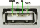 |
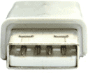
Male plug (top) and female receptacle (bottom), seen from the front. Pin 1 is at the left of the receptacle; the plug is a mirror image.
| Pin | Name | Direction | Color | Description |
|---|---|---|---|---|
| 1 | VBUS | red | +5 V power | |
| 2 | D- | ←→ | white | Data - |
| 3 | D+ | ←→ | green | Data + |
| 4 | GND | black | Ground |
USB 2.0 Type B pinout
 |  |
| Pin | Name | Direction | Color | Description |
|---|---|---|---|---|
| 1 | VBUS | red | +5 V power | |
| 2 | D- | ←→ | white | Data - |
| 3 | D+ | ←→ | green | Data + |
| 4 | GND | black | Ground |
USB Mini-B and Micro-B pinout
 |
Mini-B and Micro-B have the same five signals in the same order; only the housing differs.
| Pin | Name | Direction | Color | Description |
|---|---|---|---|---|
| 1 | VBUS | red | +5 V power | |
| 2 | D- | ←→ | white | Data - |
| 3 | D+ | ←→ | green | Data + |
| 4 | ID | any | Host/slave detect (USB OTG ID): connected to GND in an A plug, open in a B plug | |
| 5 | GND | black | Ground |
USB 2.0 header pinout (motherboard)
Internal USB 2.0 ports on a motherboard end in a 2x5 pin header that carries two ports. The layout below is the one from the Intel Front Panel I/O Connectivity Design Guide, which almost all boards and case cables follow: odd pins belong to the first port, even pins to the second, and pin 9 is removed as a key so that a 10-hole plug can only go on one way. Check your board manual before connecting a cable with separate single-pin plugs.
| Pin | Signal | Port | Pin | Signal | Port |
|---|---|---|---|---|---|
| 1 | VBUS (+5 V) | 1 | 2 | VBUS (+5 V) | 2 |
| 3 | D1- | 1 | 4 | D2- | 2 |
| 5 | D1+ | 1 | 6 | D2+ | 2 |
| 7 | GND | 1 | 8 | GND | 2 |
| 9 | Key (no pin) | 10 | No connect (shield on some boards) |
USB 2.0 wire colors
Inside a standard cable the four wires use the colors from the USB specification: red is VBUS (+5 V), black is ground, white is D- and green is D+. A bare drain wire and a foil or braid shield connect the metal shells of the two plugs. Charge-only cables omit the white and green wires. Cheap cables do not always follow the colors, so when a cable is cut open, confirm the power pair with a meter: about 5 V between red and black while the plug is in a powered port. The data pair cannot be identified with a meter; use the pin positions in the tables above.
Electrical parameters
| Parameter | USB 2.0 value |
|---|---|
| VBUS voltage | 5 V nominal; 4.75 to 5.25 V at a high-power port, 4.40 V minimum at a low-power (bus-powered hub) port |
| Current per port | One unit load is 100 mA. A device may draw 100 mA before it is configured and up to 5 unit loads, 500 mA, after the host has accepted its configuration. In suspend: 500 µA, or 2.5 mA with remote wake-up enabled |
| Charging | Up to 1.5 A from a dedicated charging port or a charging downstream port (USB Battery Charging 1.2). A dedicated charger signals itself by shorting D+ to D- through 200 Ω or less |
| Data lines | D+ and D- form one twisted differential pair; characteristic impedance 90 Ω ±15 % |
| Signal levels | Low and full speed: single-ended 0 to 3.3 V (high at 2.8 V or more, low at 0.3 V or less). High speed: ±400 mV differential on 45 Ω terminations |
| Speed detection | A full-speed device pulls D+ up to 3.3 V through 1.5 kΩ; a low-speed device pulls D- up instead. A high-speed device starts as full speed and switches to 480 Mbit/s after a "chirp" handshake during reset |
| Cable length | 5 m for full and high speed, 3 m for low speed. Up to 5 hubs may be chained, so host and device can be about 30 m apart with hubs every 5 m |
| Wires | Data pair 28 AWG, twisted; power pair 20 to 28 AWG depending on the cable length (thicker for 5 m); aluminium foil shield with a drain wire, plus a braid on full- and high-speed cables |
| Bus | Tiered star, up to 127 devices per host controller; half duplex, host controlled |
USB speeds, all versions
| # | Version | Speed |
|---|---|---|
| 1 | USB 1.x Low-Bandwidth 1996 | 1.5 Mbit/s (192 kB/s) |
| 2 | USB 1.x Full-speed 1996 | 12 Mbit/s (1.5 MB/s) |
| 3 | USB 2.0 Hi-speed 2000 | 480 Mbit/s (60 MB/s) |
| 4 | USB 3.0 SuperSpeed 2008 (renamed USB 3.2 Gen 1) | 5 Gbit/s (625 MB/s) |
| 5 | USB 3.1 Gen 2 SuperSpeed+ 2013 (renamed USB 3.2 Gen 2) | 10 Gbit/s (1,250 MB/s) |
| 6 | USB 3.2 Gen 2x2 2017, Type-C connector only | 20 Gbit/s (2,500 MB/s) |
The figures are the raw bit rates on the wire. Protocol overhead leaves roughly 35 MB/s usable on USB 2.0 and about 400 MB/s on USB 3.0 in practice.
Questions
Which USB wire is positive, and what are the wire colors?
Red is positive: it carries VBUS, +5 V. Black is ground. White is D- and green is D+, the two data wires. In a charge-only cable only red and black are present. See the wire colors section above for how to check a cable whose colors do not match.
What is the difference between USB Type A and Type B?
Type A is the flat plug on the host side; the receptacle is on PCs, hubs and chargers. Type B is the square plug on the device side; the receptacle is on printers, instruments and the upstream port of a hub. Electrically they carry the same four signals with the same pin numbers, so an A-to-B cable is a straight connection. The two shapes exist so that a host is never cabled to another host.
What does the ID pin on Mini and Micro USB do?
Pin 4 of a Mini or Micro connector tells an OTG-capable device which role to take. In a Mini-A or Micro-A plug the ID pin is wired to ground, and the device that receives it becomes the host and supplies VBUS. In a Mini-B or Micro-B plug the ID pin is left open, and the device stays a peripheral. Ordinary phones, cameras and instruments with a Micro-B port never use the ID pin unless an OTG adapter is plugged in.
How long can a USB 2.0 cable be?
5 m for full-speed and high-speed devices, 3 m for low-speed devices such as keyboards and mice. The limit comes from signal timing, not from the wire itself, so a longer passive cable may work with one device and fail with another. To go further, put a powered hub every 5 m (up to five hubs), use an active extension cable, which contains a hub, or use a USB extender that sends the bus over Ethernet cable or fibre.
How much current does a USB 2.0 port supply?
Up to 500 mA after the device has been configured, 100 mA before. A charging port that follows USB Battery Charging 1.2 supplies up to 1.5 A. A USB 3.0 port supplies 900 mA to a SuperSpeed device, and a USB Type-C port with Power Delivery negotiates much more. Many PC ports deliver more than 500 mA in practice, but a device that depends on it is outside the specification.
Is USB 2.0 half duplex or full duplex?
Half duplex. There is one differential pair, D+ and D-, and the host controls who talks: it sends a token, the device answers, and the next transfer starts. USB 3.0 adds two SuperSpeed pairs, one for each direction, and is full duplex on them.
Can a USB 2.0 device be plugged into a USB 3.0 port?
Yes. The USB 3.0 Type A receptacle keeps the four USB 2.0 contacts in the same places and adds five contacts further back, so a USB 2.0 plug fits and the device runs at its own speed. The reverse also works: a USB 3.0 Type A plug fits a USB 2.0 port and the device falls back to 480 Mbit/s. Only the Type B and Micro-B plugs of USB 3.0 are larger and do not fit USB 2.0 receptacles.
See also: USB 3.0 pinout (Type A, Type B and Micro-B with the SuperSpeed pairs), USB Type-C pinout and the RS232 pinouts for serial ports. If the problem is a device rather than a cable, the USB protocol analyzer shows the packets a device exchanges with Windows, and the USB software: sniffer, HID logger page lists the tools for logging data from USB devices.