
DB15 Serial Port Pinout: X.21 Interface and RS232 DB15 Cables
A two-row 15-pin D-sub (DA-15, usually called DB15) on a serial device is almost never RS232. It is the connector of X.21, the synchronous interface of leased-line modems, ISDN and WAN equipment and the serial ports of routers, where it appears as a "DB15 X.21 serial cable". Its electrical layer is X.27 / V.11, the same balanced signalling as RS-422, so an X.21 port cannot be wired straight to an RS232 port; a converter is needed. Two other 15-pin sockets on a PC are unrelated: the three-row HD15 of a VGA monitor and the old two-row game or MIDI port, which is not a serial port at all.
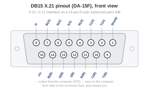
Fig. 1. DA-15 female connector as found on X.21 equipment, front view (pin 1 at the top right)
X.21 pinout on the DB15 connector (ISO 4903)
Every X.21 signal is a balanced pair: the A wire is on the top row, the B wire of the same signal is eight pins further, on the bottom row. Directions are from the DTE (router or terminal) to the DCE (modem or network termination).
| Pin | Signal | Name | Direction | Pair B on pin |
|---|---|---|---|---|
| 1 | Shield | Cable shield, chassis ground | ||
| 2 | T (A) | Transmit | → | 9 |
| 3 | C (A) | Control (the DTE is ready, like RTS/DTR) | → | 10 |
| 4 | R (A) | Receive | ← | 11 |
| 5 | I (A) | Indication (the DCE is ready, like DCD/DSR) | ← | 12 |
| 6 | S (A) | Signal element timing (bit clock) | ← | 13 |
| 7 | B (A) | Byte timing (optional, rarely wired) | ← | 14 |
| 8 | G | Signal ground | ||
| 9 | T (B) | Transmit, B wire | → | |
| 10 | C (B) | Control, B wire | → | |
| 11 | R (B) | Receive, B wire | ← | |
| 12 | I (B) | Indication, B wire | ← | |
| 13 | S (B) | Signal element timing, B wire | ← | |
| 14 | B (B) | Byte timing, B wire | ← | |
| 15 | n/c | Not assigned |
X.21 compared with RS232
RS232 uses single-ended ±12 V signals and a separate wire for every handshake line (RTS, CTS, DTR, DSR, DCD), and it is normally asynchronous: no clock is transmitted. X.21 uses balanced pairs, carries a clock from the DCE on the S pair and replaces the handshake lines by one control pair (C) and one indication pair (I). The names of the RS232 lines are explained under RS232 signals; the serial port interface page covers voltage levels and flow control.
RS232 on a 15-pin connector
There is no standard RS232 pinout for a 15-pin D-sub. Where it occurs, it is specific to one product: internal modems of the 1990s such as the Speedster 14.4 series brought their RS232 lines out on a DA-15 socket and shipped a DB9 to DB15 cable for it, and some embedded boards and industrial controllers do the same today. The RS232 modem cable (DB9-DB15) page gives that modem wiring as an example. For any other device, take the pin assignment from its manual and match the signal names against the DB9 pinout or the 25-pin RS232 pinout.
DB15 serial related links
- RS232 connector pinouts: DB9, DB15, DB25 and RJ45 compared on one page.
- Full 25-pin RS232 pinout (DB-25), the connector X.21 replaced on WAN equipment.
- RS232 RJ45 pinout: EIA-561 and Cisco console wiring.
- Modem cable DB9-DB15 for internal modems with a 15-pin socket.