
Siemens Hicom 150 Officecom SMDR setup and formats
This page covers the Siemens Siemens Hicom-150 OfficeCom v2 and Siemens Hicom-150 OfficeCom variants in Advanced PBX Data Logger. Each section gives the connection settings, the parser to select and the fields the logger extracts for reports or a database; where the setup steps are the same for every variant they are given once. The settings apply to our logger; other call accounting software may expect a different configuration.
Quick facts
| Item | Siemens Hicom 150 Officecom SMDR setup and formats |
|---|---|
| Variants on this page | Siemens Hicom-150 OfficeCom v2, Siemens Hicom-150 OfficeCom |
| Interface | Serial. The SMDR or printer port of the PBX is connected to a COM port; speed, data bits, parity and flow control must match the PBX. |
| Parsers | Siemens Hicom-150 OfficeCom v2, Siemens Hicom-150 OfficeCom |
| Fields extracted | 9 to 12 |
| Other Siemens systems | Siemens Hicom, HiPath variants and Rolm CDR formats |
Variants on this page
- Siemens Hicom-150 OfficeCom v2 · Serial, 12 fields
- Siemens Hicom-150 OfficeCom · Serial, 9 fields
Settings from the manufacturer's documentation
Taken from Siement Hicom150 progguide, smdr pinout. Values are those stated in the documentation; confirm them against your firmware release.
| Setting | Documented value |
|---|---|
| serial parameters (optiset E control adapter / UP0-E "Printer Pipe Mode" CDR output) | Fixed at 9600 baud, no parity, 8 data bits, 1 stop bit (9600,N,8,1) — not configurable |
| configurable baud rate (V.24/RS-232 CDRC port) | 2400, 9600, or 19200 baud, selectable per RS-232 port used for CDRC |
| default value for incoming-call recording | No — only outgoing calls are recorded by default |
| LAN output field separator / line ending defaults | ";" is the default field separator (alternative "|"); DOS mode (CR LF) vs UNIX mode (LF only) for line endings |
| record buffer size on link failure | OfficePro buffers 300 records; OfficeCom buffers 150; OfficePoint/OfficeOne buffer 50 |
| output destination options | V.24/RS-232 API port; PC attendant console port via optiset E/UP0-E control adapter (writes Charge.dat); LAN/Ethernet (as of Release 3.0) |
| programming tool used to configure CDRC | "Hicom Assistant T" (menu-code driven) or "Hicom Assistant E Office" (menu-path driven) |
| output record format options | Compressed (for PC/call-charge computer, no separating spaces or headers) or Long (for printer, space-separated with header and form feed) |
| cable pinout, Hicom 150E variant (PBX 25-pin male to PC 9-pin/25-pin female) | PBX pin8->PC9F pin1->PC25F pin8; PBX pin2->PC9F pin2->PC25F pin3; PBX pin3->PC9F pin3->PC25F pin2; PBX pin6->PC9F pin4->PC25F pin20; PBX pin20->PC9F pin6->PC25F pin6; PBX pin5->PC9F pin7 |
Switching SMDR output on, as documented
- In Hicom Assistant T, set the CDRC print format via menu 11-3-1 (CDR - CDR, central - Print format).
- Continue CDRC setup in Hicom Assistant T with 11-3-2 (station number format), 11-3-3 (incoming call), 11-3-4 (call duration), 11-3-5 (print MSN).
- Assign the RS-232 port used for CDRC output via Hicom Assistant T menu 22-13-2-1 (System settings - CDR central), choosing port 1 to 3.
- Set the CDRC baud rate via Hicom Assistant T menu 22-13-1 (System settings - Baud rate).
- In Hicom Assistant E Office, go to System status - Call charges - Output format to configure CDRC.
- To send call data to an optiset E control adapter (Printer Pipe Mode) via Hicom Assistant T, go to 22-13 (V24 configuration), select 2 (CDRC/CDRS/CDRT/CDRA), then 1 (UP0/E port for control adapter).
- Equivalent Printer Pipe Mode setup in Hicom Assistant E Office: Call charges - Output format - Port assignment - set UP0/E port to the station number with the control adapter.
Record format notes
- Compressed-format record has 13 positional fields: Date(8), Time(8), Trunk(3), Internal station number(6), Ring duration(5), Call duration(8), Station number(25), Call charge pulses(11, blank in US), Information element(2), ACCT(11), MSN(11), Seizure code(5), LCR route(2).
- Date field is DD.MM.YY (date at end of call); time field is hh:mm:ss.
- "Information element" is a call-type code: 1=incoming voice, 2=outgoing voice, 3=incoming other services, 4=outgoing other services, 5=incoming forwarded, 6=outgoing forwarded, 7/8=conference legs, 9=outgoing via call forwarding, 0=caller-list line; +50=DISA, +20=call-setup charges.
- If the recording device/link fails, buffered records accumulate; once restored the system emits a loss-message line reporting the count, e.g. "** 100 calls lost **".
- Every record (both formats) ends with CR LF; unsupplied fields are space-filled.
- Long (printer) format prints a localized header and form-feeds after 62 printed lines (including header); the next page starts with a fresh header.
- Account code (ACCT) field is 11 digits, space-padded if shorter or absent; ACCT is omitted entirely from the Long/printer format.
Siemens Hicom-150 OfficeCom v2
Parser: Siemens Hicom-150 OfficeCom v2
Connection: Serial. The SMDR or printer port of the PBX is connected to a COM port; speed, data bits, parity and flow control must match the PBX.
Fields extracted: 12
Connection parameters
This information is applicable for all 150 series models including: Hicom 150, Hicom 150 E (150E), Hicom 150 H OfficePoint, Hicom 150 H OfficePro, Hicom 150 H OfficeCom.
In OfficeCom OfficePoint, the V24/2 module provides two serial V.24 (RS-232) interfaces for connecting a computer, a printer, or Plus Products (such as Uniform Call Distribution). The V24/1 (not for U.S.) is an under equipped version with only one V.24 (RS-232) interface.
Interfaces: V24 Interfaces (S30807-Q6916-Xxxx) Note: We recommend setting up call detail recording central (CDRC) on interface X2 of OfficeCom and OfficePoint if a V24/2 module is installed.
Use a shielded 9-pin cable as a connecting cable. The wires must be twisted and have a diameter of at least 0.5 mm (24 AWG). The integrated wire shielding must be soldered onto the connector and socket housing of both cable ends. Short-haul modems must be provided if the cable length exceeds 15 m (50 ft.).
Pinout of the V.24 (RS-232) cable for OfficePro
| 9-Pin (Female) | 25-Pin (Male) | Signal |
|---|---|---|
| 1 | 8 | DCD (Data Carrier Detect) |
| 2 | 3 | RxD (Receive Data) |
| 3 | 2 | TxD (Transmit Data) |
| 4 | 20 | DTR (Data Terminal Ready) |
| 5 | 7 | GND (Signal Ground) |
| 6 | 6 | DSR (Data Set Ready) |
| 7 | 4 | RTS (Request To Send) |
| 8 | 5 | CTS (Clear To Send) |
| 9 | 22 | RI (Ring Indicator) |
Pinout of the V.24 (RS-232) cable for OfficeCom and OfficePoint

Data items: Siemens Hicom-150 OfficeCom v2
| Description | Data type | Column name |
|---|---|---|
| Call time | datetime | CALL_TIME |
| Trunk | string | TRUNK |
| Extension | string | EXT |
| Ring | datetime | RING |
| Call duration | datetime | CALL_DURATION |
| Call duration (s) | integer | CALL_DURATION_S |
| Phone | string | DIALED_PHONE |
| Call type | string | CALL_TYPE |
| Direction | string | DIRECTION |
| Account code | string | ACC |
| Flag 1 | string | FLAG1 |
| Flag 2 | string | FLAG2 |
Sample record
As delivered by the system; phone numbers, names and public addresses are masked.
16.11.1016:25:59  5   206     00:00:096xxxxxxx                             2                          0 1
16.11.1016:33:38  5   203     00:02:006xxxxxxx                             2                          0 1
16.11.1016:34:13  6   237     00:02:376xxxxxxx                             2                          0 1
Siemens Hicom-150 OfficeCom
Parser: Siemens Hicom-150 OfficeCom
Connection: Serial. The SMDR or printer port of the PBX is connected to a COM port; speed, data bits, parity and flow control must match the PBX.
Fields extracted: 9
Connection parameters
This information is applicable for all 150 series models including: Hicom 150, Hicom 150 E (150E), Hicom 150 H OfficePoint, Hicom 150 H OfficePro, Hicom 150 H OfficeCom.
In OfficeCom OfficePoint, the V24/2 module provides two serial V.24 (RS-232) interfaces for connecting a computer, a printer, or Plus Products (such as Uniform Call Distribution). The V24/1 (not for U.S.) is an under equipped version with only one V.24 (RS-232) interface.
Interfaces: V24 Interfaces (S30807-Q6916-Xxxx) Note: We recommend setting up call detail recording central (CDRC) on interface X2 of OfficeCom and OfficePoint if a V24/2 module is installed.
Use a shielded 9-pin cable as a connecting cable. The wires must be twisted and have a diameter of at least 0.5 mm (24 AWG). The integrated wire shielding must be soldered onto the connector and socket housing of both cable ends. Short-haul modems must be provided if the cable length exceeds 15 m (50 ft.).
Pinout of the V.24 (RS-232) cable for OfficePro
| 9-Pin (Female) | 25-Pin (Male) | Signal |
|---|---|---|
| 1 | 8 | DCD (Data Carrier Detect) |
| 2 | 3 | RxD (Receive Data) |
| 3 | 2 | TxD (Transmit Data) |
| 4 | 20 | DTR (Data Terminal Ready) |
| 5 | 7 | GND (Signal Ground) |
| 6 | 6 | DSR (Data Set Ready) |
| 7 | 4 | RTS (Request To Send) |
| 8 | 5 | CTS (Clear To Send) |
| 9 | 22 | RI (Ring Indicator) |
Pinout of the V.24 (RS-232) cable for OfficeCom and OfficePoint
Data items: Siemens Hicom-150 OfficeCom
| Description | Data type | Column name |
|---|---|---|
| Call time | datetime | CALL_TIME |
| CO | string | TRUNK |
| External | string | EXT |
| Ring | datetime | RING |
| Call duration | datetime | CALL_DURATION |
| Call duration (s) | integer | CALL_DURATION_S |
| Phone | string | DIALED_PHONE |
| Call type | string | CALL_TYPE |
| Direction | string | DIRECTION |
Connecting the logger
All variants on this page use the same connection settings; the steps below apply to each of them.
Configuring a COM port
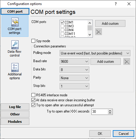
The COM port number should match the number in your system. You can check the correct port number in Devices Manager → Ports.
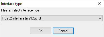
1. Add a new configuration with the RS232 data source (if you didn't it before).
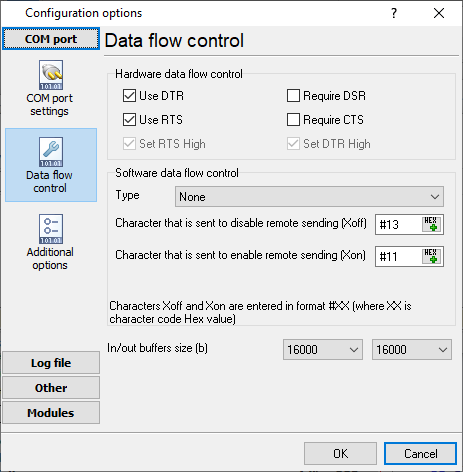
2. Select the COM port and configure the communication settings for your PBX corresponding to your PBX settings.
Selecting the correct parser for Siemens Hicom-150 OfficeCom v2
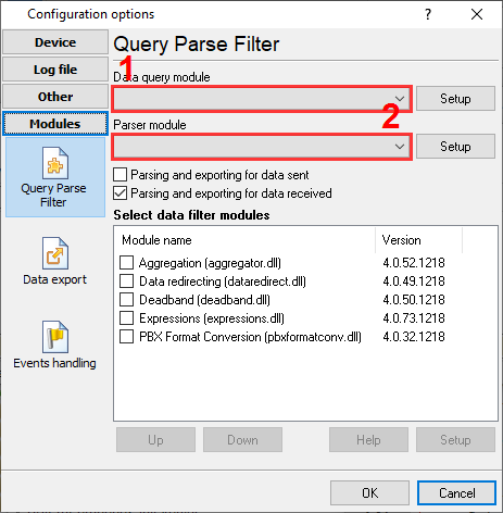
Siemens Hicom-150 OfficeCom v2
Siemens Hicom-150 OfficeCom v2
Reports and a database
Once records arrive, the logger writes them to a text file or to any ODBC database in real time, or hands them to the PBX Reports utility for manual, scheduled and e-mailed reports with a built-in web server. See exporting call log data to a database for the database setup.
Related Siemens systems
Siemens Hicom-118Siemens HiPATH 1100
Siemens Hicom-250
Siemens Hicom, HiPath variants and Rolm CDR formats
Siemens Hicom-300E (ANI format)
All supported PBX systems
Note: Products and companies mentioned here are used only for definition and identification purposes and can be trademarks and/or registered trademarks of the respective companies.
Related topics: Advanced PBX Data Logger
hereCall logging Call accounting SMDR to SQL SMDR Listener Cables and signals