
OPC server for intelligent length meter
Task
I would like to make an OPC server for my intelligent length meter with a RS232 interface and transfer this data to the SCADA, since there is no a manufacture's OPC server for this meter.
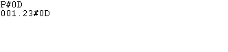
Fig. 1. Data from a length counter device. Type 1.
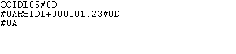
Fig. 2. Data from a length measuring device. Type 2.

Fig. 3. Digital length counter meter data. Type 3.
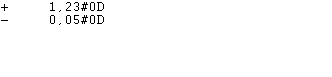
Fig. 4. Intelligent length meter data. Type 4.
Requirements
- Advanced OPC Data Logger Professional, Enterprise, or a trial version;
- ASCII Data Parser and Query plugin for Data Logger.
- OPC DA Server plugin (built-in).
- Expressions plugin (for post-processing, exists in the standard installation package).
- OPC UA Server for Data Logger (install it additionally).
Configuring the length counter meter
Usually, smart length meters can work in two modes, which you can select in the meter settings in runtime or during initial programming:
- Continuous. The length counter outputs non-stop data, without requests from the computer's side.
- By request. The length counter outputs data after a special request from a computer. Usually, it is a command like P<CR><LF> (the short form of Print) or S<CR><LF> (the short form of Start). <CR> and <LF> are ASCII symbols that terminate a single line of data with hexadecimal codes 0x0D and 0x0A, respectively. In this mode, you can control a polling interval and a data collection rate.
Tip: If the communication parameters or command format for your length counter are not known, but you have a manufacturer's software, you can use it together with our Advanced Serial Port Monitor utility running in the "Spy" mode, to watch and inspect a data exchange protocol between the meter and the computer.
Solution
1. First, you should try to receive data from your intelligent length meter. Please create a new configuration in the main window (the "Plus" button) and configure communication parameters on the "COM port" tab (fig. 5).

Fig. 5. Communication settings for an intelligent length meter.
2. If your meter requires a special command, go to the "Modules → Query Parser Filter" tab and enable the "ASCII Data Query" plugin. Then open its settings to add a request and configure a polling interval (fig. 6-8). You can set a larger interval on the testing stage.

Fig. 6. Enabling the data query plugin.

Fig. 7. Adding a data request.
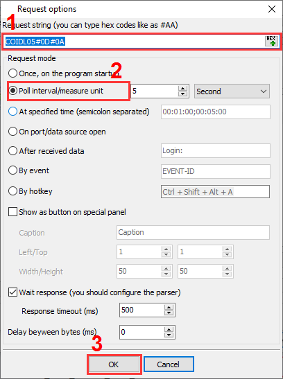
Fig. 8. Request parameters.
3. Ensure that you receive data from your length meter device in the main window (fig. 1-4). It means that you've configured communication parameters and an optional request correctly, and you may continue configuring a parser plugin and preparing a value for the OPC server.
4. Now, it is necessary to find out beginning and ending signatures of data packets. The program will use them to separate data blocks from a data flow. To achieve this, you can enable the "Display data before parsing" option and additionally change mode for ASCII characters with code lower than 0x20h (fig. 9). Usually, simple software protocols use ASCII control characters to frame a data packet. Figures 1-4 with data examples above show control characters #0D, #0A, #03, and they correspond to ASCII characters <CR>, <LF>, <ETX>.
Note: You can select other data view mode in production because this mode does not affect on the OPC server operations.

Fig. 9. Data view mode setup.
5. Now, go to the parser configuration, which is responsible for extracting the desired meter value from a data packet. Select the "ASCII data parser and query" plugin from the "Parser module" list (fig. 10), select the "Parsing and exporting for data received" option, and click the "Setup" button.

Fig. 10. Selecting the parser.
6. Data examples above (fig. 1-4) have a simple format. Every record has a fixed length and meter value is always located at a fixed position, aligned to the right side. A manufacturer may use spaces or zero to align a value.
When you changed the data view mode, our software displays all ASCII control characters like a hex code #00. It is obvious, a data packet has the following framing characters for the corresponding data type, which you should copy to the parser settings (fig. 11):
- Beginning signature: none, ending signature: #0D#0A.
- Beginning signature: RSIDL, ending signature: #0D#0A.
- Beginning signature: #02, ending signature: #03#0D.
- Beginning signature: none, ending signature: #0D.

Fig. 11. Parser settings.
7. The next step is adding a parser variable, which will appear in the OPC server (fig. 12). To calculate a precise fixed position in a data packet, you can copy the whole data packet from the main window to Notepad. You can easily count where a meter value starts (fixed position) and what is the maximum length of that value (fixed length). Please note, you should skip the beginning signature of your data packet (discard them), and all control characters like #00 allocate only one position in a source data packet instead of three positions in the main window. Thus, for data packets on fig. 1-4 variable parameters will look like:
- Fixed position: 1, fixed length: 6.
- Fixed position: 1 (discarded characters are RSIDL), fixed length: 11.
- Fixed position: 6 (discarded one ASCII characters of the beginning signature, skipped 5 unnecessary header characters), fixed length: 6.
- Fixed position: 1, fixed length: 10.
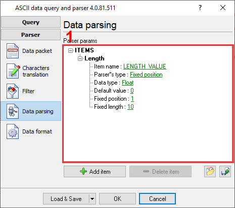
Fig. 12. Parser variable.
8. Post-processing. Sometimes, a source value in a data packet does not include a decimal point, and it is necessary to modify it before exporting to the OPC server. For example, in the data example 3, the last two numbers are the decimal part of a meter value. Therefore, we should divide the extracted value by 100. You can do it using the Expressions filter plugin (fig. 13-14).

Fig. 13. Selecting the filter plugin for post-processing.
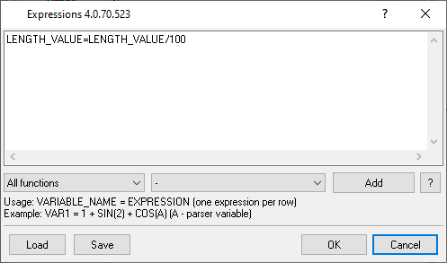
Fig. 14. Defining a formula for post-processing.
9. On the final stage, you should configure the OPC server. Go to the "Modules → Data export" tab and place a mark before the necessary server type (fig. 15). You can select both OPC server types (DA & UA). They can work at the same time.

Fig. 15. Enabling the OPC server.
10. Open the OPC server configuration window (fig. 16) and enable data grouping by a data source name (by a COM name). It allows you to connect several measuring devices to one computer and get different OPC tags in the OPC server because they will appear in different groups.

Fig. 16. OPC data grouping.
11. We recommend predefining the important OPC tags with meter values (one per meter) on the corresponding tab (fig. 17) because an OPC client can connect to the OPC server before the logger received a first value from a meter and a variable will appear in the OPC server. All predefined variables will be added to the server with an empty value.

Fig. 17. Predefining OPC tags.
12. Finally, click "OK" in all dialog windows to save the settings and complete your setup. Wait for incoming data and open the OPC server configuration window again on the "Active items" tab. There you can see all OPC tags and their values (fig. 18). Now, your OPC client or SCADA can connect to the OPC server and subscribe to the necessary OPC tags.

Fig. 18. Tags in the OPC server.
FAQ
What length meters or counters can I connect? Do you have a list of supported models?
The main requirement is the RS232 or RS485 interface in your meter. We do not have a precise list because there are models on the market from many manufacturers. Usually, the model name does not include info about the interface type.
How many digital length counters or meters can I poll?
Our software can poll up to 100 identical meters on one computer. This limit significantly depends on your computer performance and complexity of your data logger configurations. Different length meter types also decrease this limit.
Another program already reads data from my length measuring device? Can I get a copy of this data?
You can solve this problem using two methods:
- Programmatically. If that program works on Windows, you can install our software on the same computer and use the "Spy" mode of our logger, which you may enable in the COM port settings (fig. 5). Our software should start first, before another program start using a COM port.
- Using additional hardware. You may make a special data monitoring cable and install our software on an additional computer with Windows, and connect a monitoring tap there.
Another program polls a meter too quickly. Can I decrease data logging rate?
We have additional data filter plugins. You can use the Deadband plugin for this task, where you can filter out data by a timeout or control value change.
Related articles: OPC server for intelligent length meter
Related topics: Advanced OPC Data Logger
hereOPC Logger RS232 pinout and signals Cables and signals Data monitor cables